Digital twin of masonry stone wall (Rhino) - Layers allignment
For more info: andrea.settimi@epfl.ch
This tutorial has been realized by IBOIS by the collaboration with the laboratory EESD (PI: savvas.saloustros@epfl.ch) in a joint effort of digitzing a masonry wall. The goal of this tutorial series is to help users to reconstruct step by step the process of post-processing cleaning, segmentation, and reconstruction of scanned point cloud data to reconstruct a twin digital wall of a physical masonry artifact.
The tutorial is divided in 3 parts (a,b,c). The first part (a) illustrates how to digitize and build a stone data set, the second (b) shows how to reallign multiple scans into the same coordinate system and finally (c) we relocate the stone model into the wall landscape.
💬 To be able to reproduce these tutorials you will need the WIP version of Cockroach. Download Cockroach from food4rhino and replace the .rhp file with this one here. This version will be soon stable and released.
Scanning of wall layers
This second section of the tutorial illustrates how to allign all the scans of the wall layers to the same coordinate system.
During the fabrication of the wall, each layer needs to be digitized. It is often the case that, independently from the scanning technique you are using, scans will be offset one to another. Our goal here is to re-align all the scanss to the same coordinate system in order to reconstruct a wall layer by layer. To help in this task we are going to use fiducial markers which have been designed to be detected in any point cloud, independently from the hardware employed to obtain it.
You can download it here:
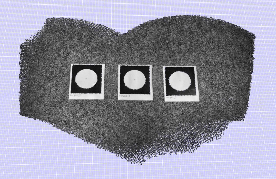
Be sure to include the markers in the field of view during the scanning: they need to be present in the scan.
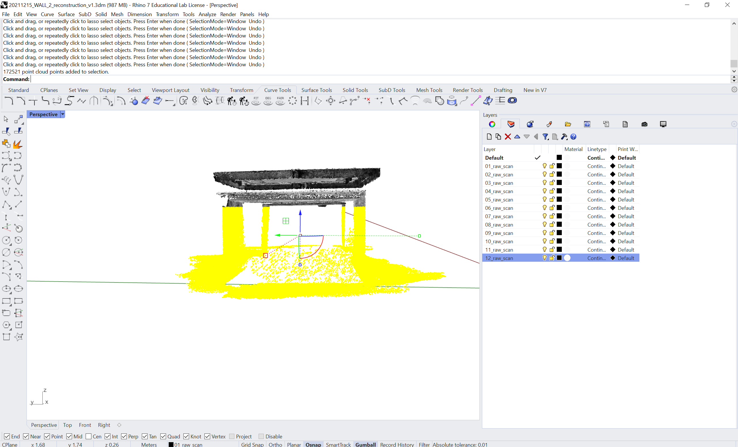
Cleaning the point cloud layers
First we need to clean the part of the point cloud that we don’t need and occupy needless memory. We need to keep the markers and the walls. What is underneath, we erase it. You can move your camera view to a lateral position where you can have a nice selection of the portion we want to delete.
To select, press Ctrl + Alt while dragging a selection with your left mouse button. See the image below to see the type of selection we need to clean. Next, you just click delete or erase space.
Now we need to divide each scan in 2 portions.
- The two parts containing the circle markers
- The central part containing the wall
To do so we are going first to draw a box with command:
Box
Place the box in a way to contain the central part of the wall.
Then, type the following in the command bar of Rhino:
Cockroach_crop
Select first the point cloud and then the box, at that’s it we divided the cloud in two parts. This is what it should like once you finished with the command. Now you can either delete the box or move it to the next cloud to repeat the same procedure.
Marker detection
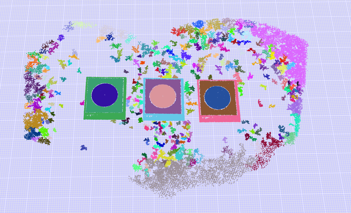
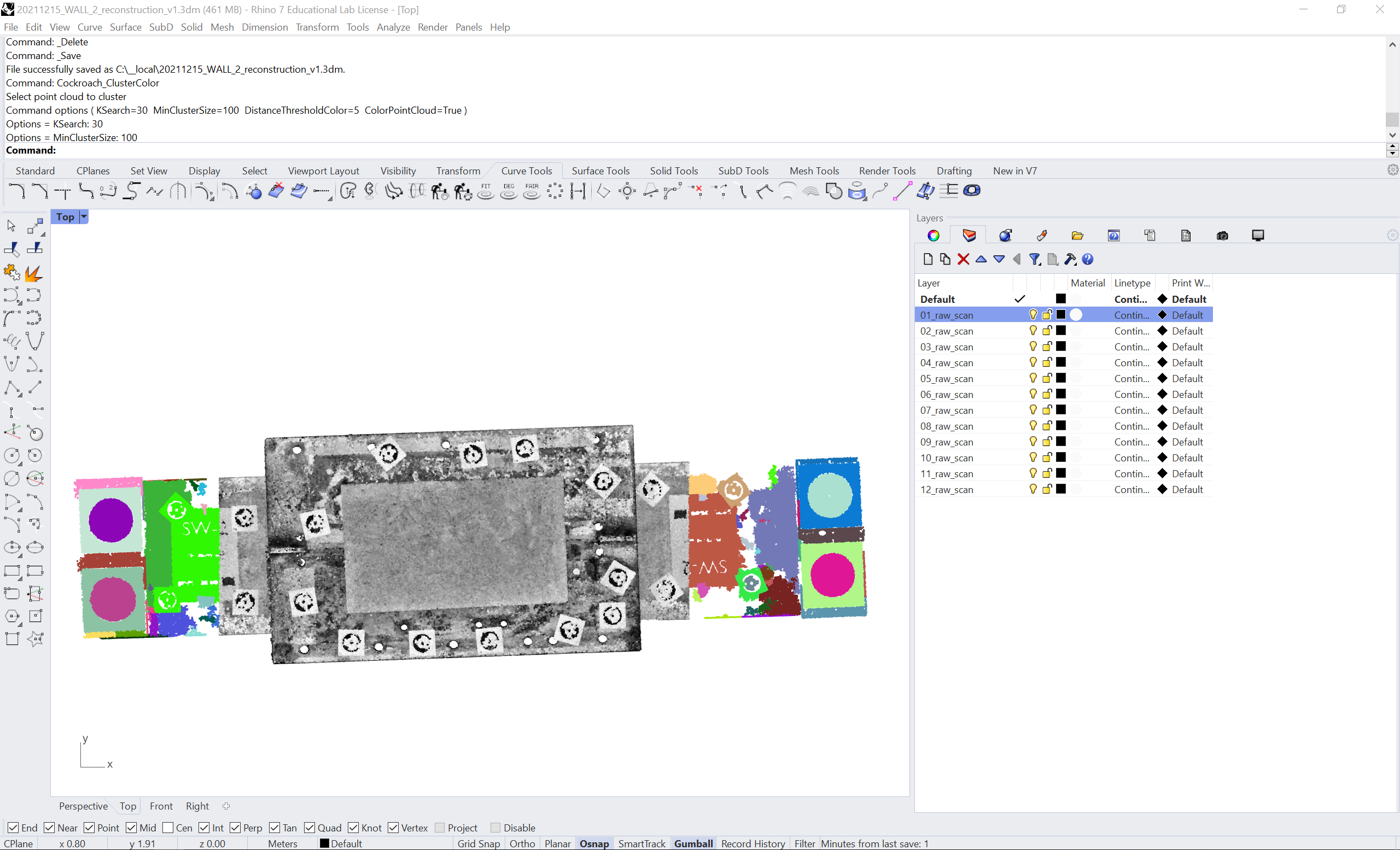
Now we are going to cluster (segment, divide in parts) the portion with the markers. To do so, we are going to use a color-based clustering command with:
Cockroach_ClusterColor
This is what the colored cluster should look like:
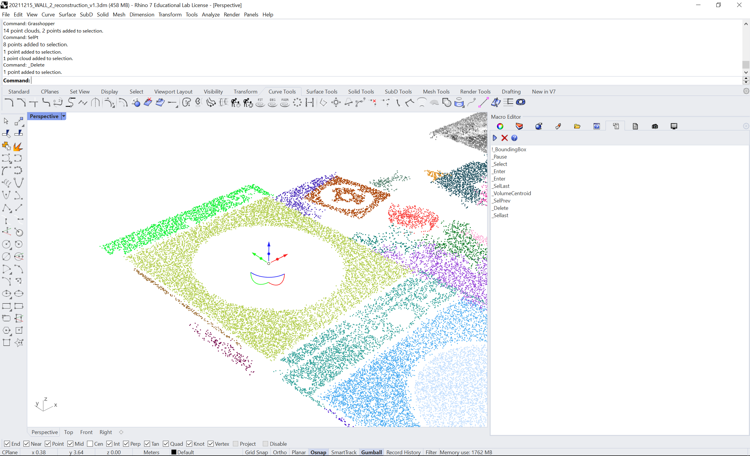
Ungroup the colored cloud with Shift + Ctrl + G. Now we need to get the centers of each circle. To achieve this we need to create a bounding box of the circle (to take in account of all different orientations of the plane on which the points of the circles are). Run the following macro in Rhino (what’s_a_macro?)
!_BoundingBox
_Pause
_Select
_Enter
_Enter
_SelLast
_VolumeCentroid
_SelPrev
_Delete
_Sellast
This is the result of the macro:
Transformation plane to plane
Now we need to use the marker central points as a reference to apply transformation plane to plane to bring all the layers to a common coordinate system. The following command and script will do everythin, you just have to follow the instruction on the command line. But, for some context, here’s what it does: we fit one plane each to 3 sets of points and apply a plane-to-plane transformation to a target point cloud (the point cloud moving).
Type the following command in the Rhino shell:
EditPythonScript
In the python Editor, paste the following code and press the play button (▶):
import Rhino
import rhinoscriptsyntax as rs
import scriptcontext as sc

# Get target point cloud (it won't move) and its marker points and fit plane
pcd_target = rs.GetObject(message="Select target point cloud (it won't move)",
                          filter=rs.filter.pointcloud)

pts_target = rs.GetObjects(message="Select marker central points of the target layer",
                      filter=rs.filter.point,
                      select=False, objects=None,
                      minimum_count=3,
                      maximum_count=3,
                      custom_filter=None)

if pts_target:
    pln_target = rs.PlaneFromPoints(pts_target[0], pts_target[1], pts_target[2])

# Get source point cloud (it will move) and its marker points and fit plane
pcd_source = rs.GetObject(message="Select source point cloud (it will move)",
                          filter=rs.filter.pointcloud)

pts_source = rs.GetObjects(message="Select marker central points of the source layer",
                          filter=rs.filter.point,
                          select=False, objects=None,
                          minimum_count=3,
                          maximum_count=3,
                          custom_filter=None)

if pts_source:
    pln_source = rs.PlaneFromPoints(pts_source[0], pts_source[1], pts_source[2])

# Apply transformation plane to plane
x_pln_to_pln = Rhino.Geometry.Transform.PlaneToPlane(pln_source, pln_target)
rs.TransformObject(pcd_source, x_pln_to_pln)
🔑To have a better reallignement it’s important that when you pick up the 3 points you pick them in the same following order for both target and source cloud (see image below). In this way the plane is better fit among the set of points.
Keep going and do the rest for all the layers. At the end you should have a full stacked wall like the animation in the introduction of this tutorial.